Balanced ATU Design
Fabricating A Balanced ATU by Gary Baker, K7EMF
There are three major reasons to utilize a “balanced” ATU:
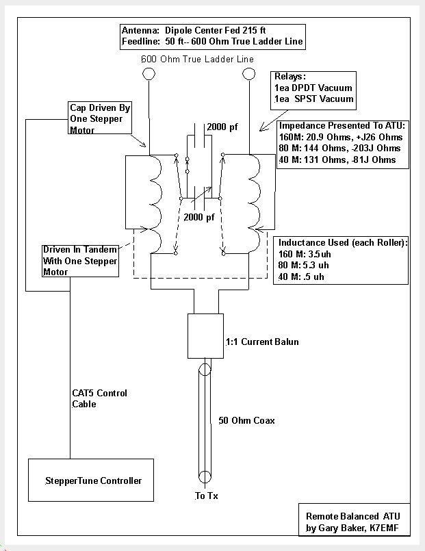
1) The balun is placed in a 50 ohm “matched” (low swr) position in the circuit. This allows the balun to do it’s job, namely to convert the RF energy from unbalanced (Coax) into a true 180 deg out of phase (one lead referenced to the other lead of the ladder line) and exactly the same amplitude. By doing this, the balanced line (TrueLadderLine) is operating in a “symmetrical mode” and thus minimal feedline radiation and minimal extraneous noise pickup in receive.
2) Low SWR (typically 1:1 match) on the balun eliminates core heating when operated within the power handling specifications of the balun. Eliminates core saturation which also eliminates harmonic generation due to no wave distortion.
3) Very broad low SWR bandwidth (see plots below) which allows for some QSY'ing without adjusting the ATU.
Commercially built ATU’s typically can accommodate a moderate impedance range where as home brew ATU’s can be designed to accommodate a wide range of impedances which will probably be encountered with 600 ohm ladder line feeding a non-resonant multiband center fed dipole. I personally prefer to fabricate my ATU so it is able to resolve these wide range of impedances and therefore do not need to respect the “feedline taboo lengths” that are published.
Designing A Balanced ATU:
In order to design the ATU, I first model the antenna I wish to erect using EzNec. Within EzNec, I perform a SWR Sweep which gives me the feed point impedance of the antenna at a given frequency (see SWR plot below). Once armed with this info, I then enter this impedance into TLD (Transmission Line Details). With the load impedance, feedline type (generic 600 ohm ladder line) and feedline length loaded into TLD, several bits of data are available (see example below):
1) Impedance at the far end of the feedline (impedance presented to the ATU).
2) Transmission system efficiency (ATU to Antenna--this is an indicator of how your antenna will function).
Now that I have the impedance presented to the ATU for each band I wish to operate this antenna on, I use another freeware called “SimSmith” (see example below). I choose my circuit elements by dragging and dropping into the circuit. Typically for this application, I us a unbalanced “L” network. The “generator” side of the circuit is 50 ohms 0J Ohms. The “load” side of the circuit is set to the impedance provided by TLD. Then I use the right mouse button in a “drag” mode to move the plot to the 50 ohm, non-reactive location on the Smith Chart. Final step—pull the values off the display for the inductor and capacitor design for the ATU.
By attacking this issue in this manner and using vacuum relays in lieu of AC Contactors, I am able to see return loss numbers in the order of 70 db! It has not been necessary to adjust feedline length or antenna length to modify the impedances presented for 160M through 40M.
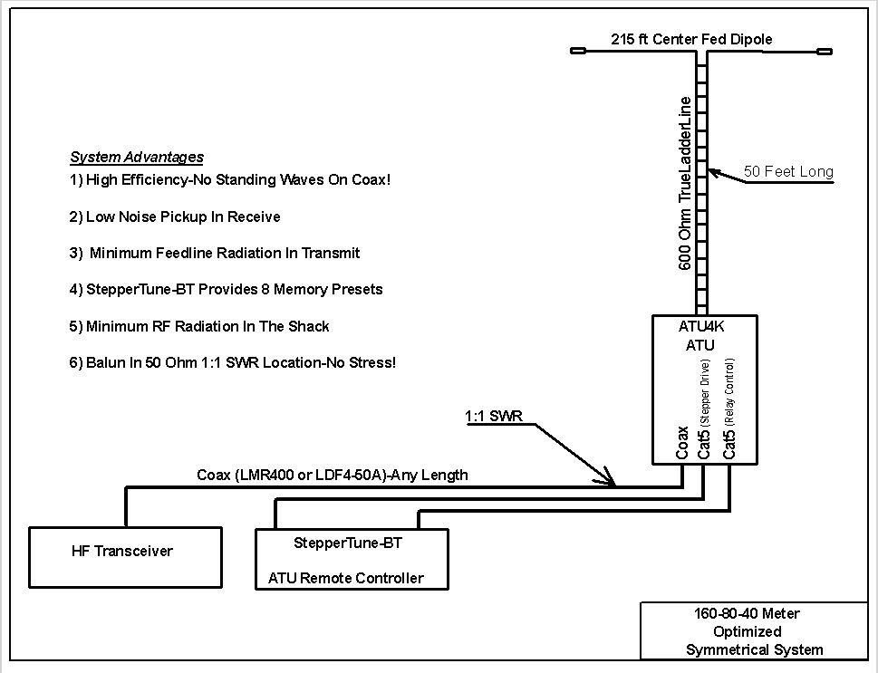
Since I cannot bring the TrueLadderLine directly into the shack, I terminate the ladder line feed into the ATU which is located at the base of my antenna support structure (Tower Base). From there I use high quality coax like Andrew LDF4-50A (LMR400 is next best) to the radio room. By remotely locating my ATU, I eliminate standing waves on the coax thus eliminating mis-matched losses of the coax!
Because the ATU is remotely located, I use a StepperTune to control the two stepper motors within the ATU. StepperTune has 8 memories which I use to “preset” the ATU to memorized operating frequencies. I only need to “touch up” the SWR if I QSY significantly from the memorized settings for each of the bands of operation. StepperTune is described at www.steppertune.com and is sold here on the W7FG TrueLadderLine and Antennas store.
New "StepperTune":
The balanced ATU requires vacuum relay control to switch between high and low impedance and the amount of capacitance to be used. The new StepperTune-BT is capable of controlling up to three vacuum relays. The three relay driving circuits will be associated with each memory position. When the operator selects a memory for a particular band, the correct vacuum relays within the ATU are automatically actuated for that band by Steppertune-BT. By using StepperTune-BT to perform this task along with actuating the stepper motors, the operator no longer needs a seperate switch control panel to actuate the vacuum relays within the ATU. StepperTune-BT is now listed in our store!
This is the preferred interconnection for the ATU and StepperTune-BT:
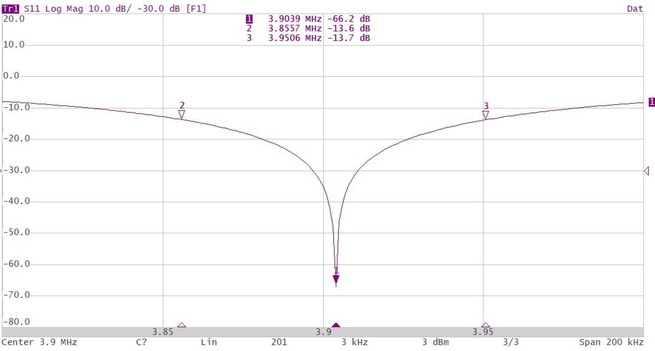
Antenna System Bandwidth In Terms Of Return Loss (db) 13.6db=95 Khz
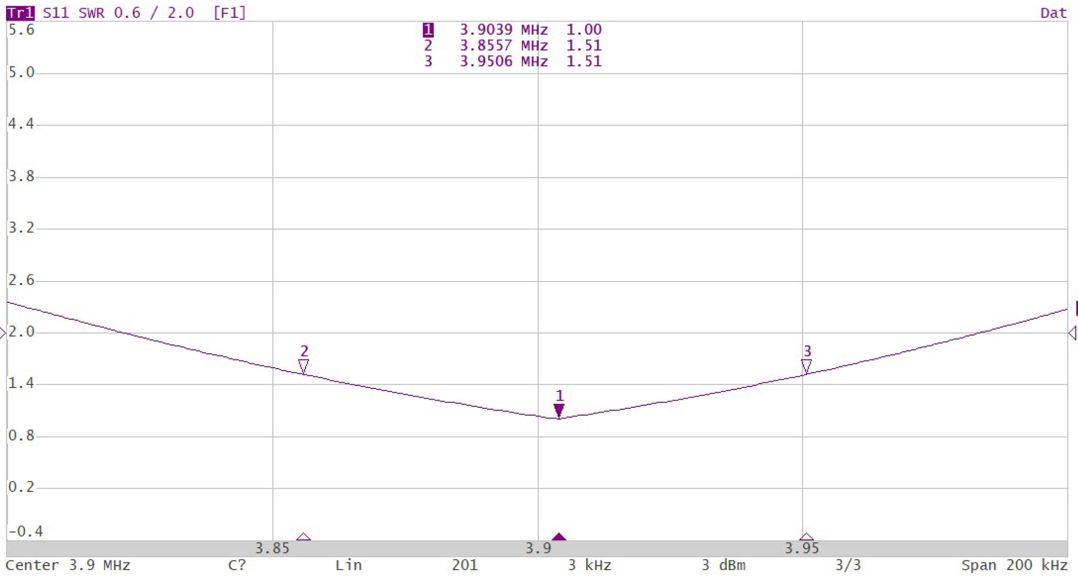
Antenna System SWR Bandwidth In Terms Of SWR 1.5:1=95 Khz
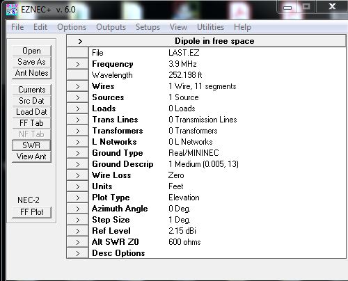
EzNec Setup-215ft Dipole Center Fed
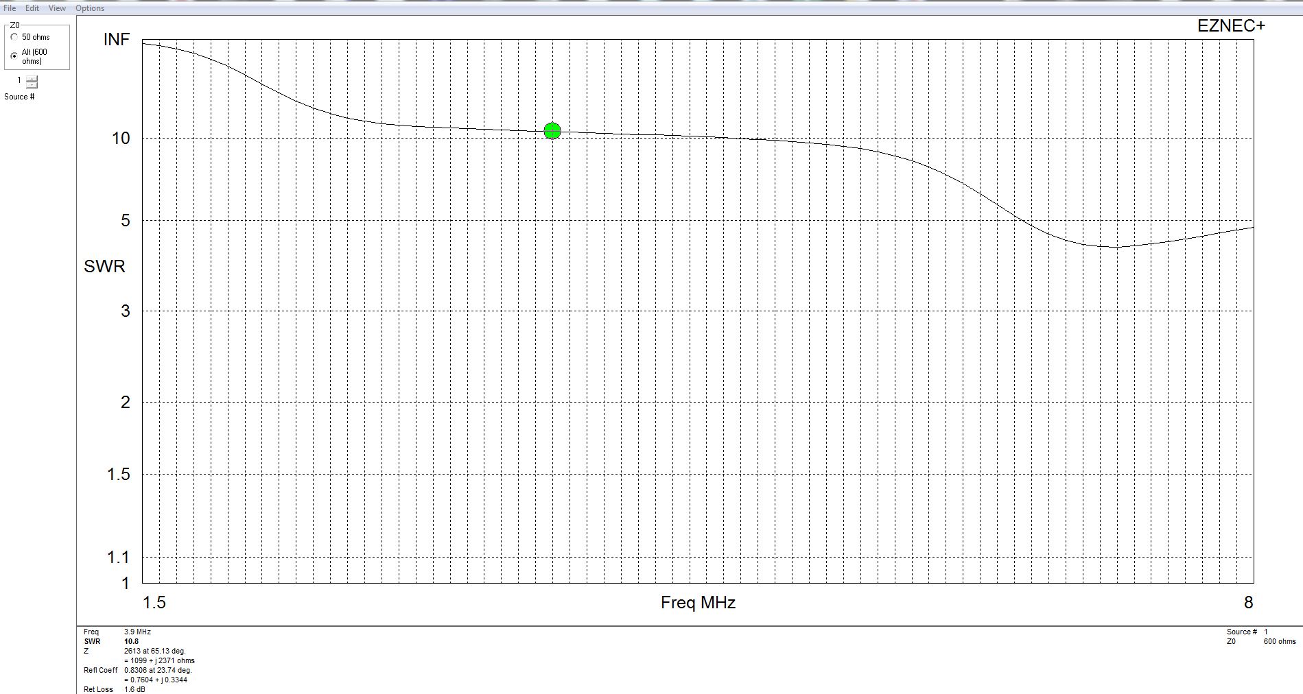
EzNec SWR Sweep For 215ft Center Fed Dipole (3.9Mhz)
Impedance Derived: 1099 Ohms Resistive, +J2371 Ohms (Loaded Into TLD Below)
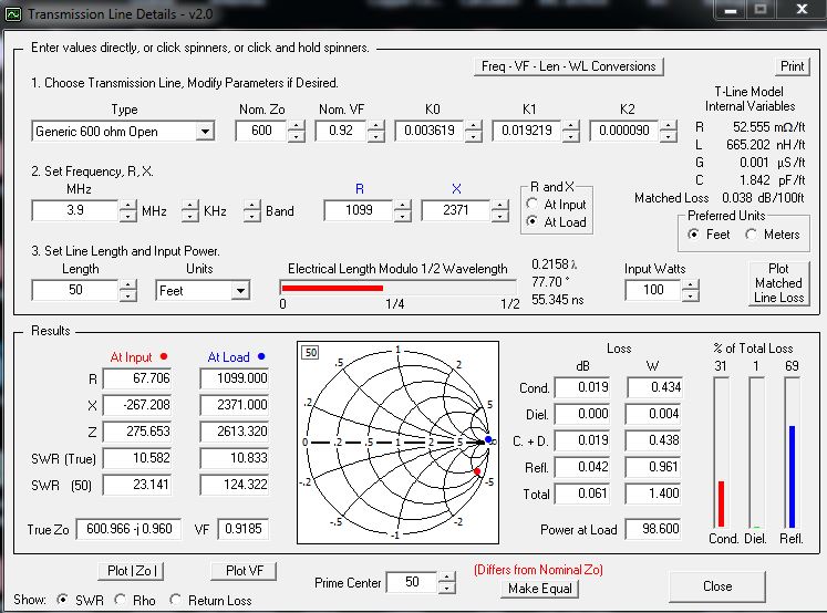
Efficiency Model (TLD) For 215ft Dipole and 50ft of TrueLadderLine (98.6% !)
(Input Power 100 Watts--98.6 Watts To The Antenna)
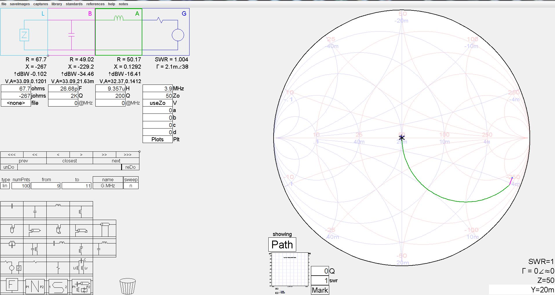
SimSmith Used For “L Network” For 75 Meters ATU (215 Ft Dipole-50 Ft TrueLadderLine)
Resultant ATU Design Model-Inductors: 9.35/2=4.7uh each Capacitor: 27pf
-----------------------------------------------------------------------------------------------------------
StepperTune-Two Stepper Motor Controller
StepperTune Features:
--Designed To Control Two Stepper Motors For Controlling A Remotely Located Antenna Tuner.
--May Remotely Control Tuning Capacitor For Magnetic Loop.
--Control Cable May Be CAT5 Cable Up To 200 ft while Using A 12 Volt Power Supply.
--Cable Lengths Greater Than 200 ft May Be Realized Using A Supply Voltage Up To 24 Volts DC.
--Eight Memory Locations For Both Steppers.
--Auto Band Memories For Auto-Band Change From Icom Transceivers.
--Automatic Antenna Tuning Capable With External Specified Directional Coupler Connected.
--Stepper Motor Current Control and Stepper Motor Current Displayed. Capable Of Up To 2 Amps of Stepper Drive Current.
--Stepper-Over Current/Over Temp Shutdown Protection.
--“Jog Mode” To Easily Fine Tune Either Stepper Motor.
--Stepper Motor Speed Easily Programmed.
--Limits Set In Software To Limit Travel
©
This Controller Is Capable Of Driving Two Stepper Motors Over 8 Conductor Cable (typically CAT5 cable). Current Control Is Necessary To Protect The Stepper Motors. The Display Shows Stepper Motor Position In Terms Of Step Number And Current Used For The Latest Stepper Motor Movement. This Unit Is Extremely Accurate And Re-Settable. It Utilizes Replaceable H-Driver Modules Which Are Current And Temp Protected. I Have Been Using This Controller For Four Years With 100% Functionality at the EMF Ranch. See full Description and Manual download at steppertune.com Gary, K7EMF
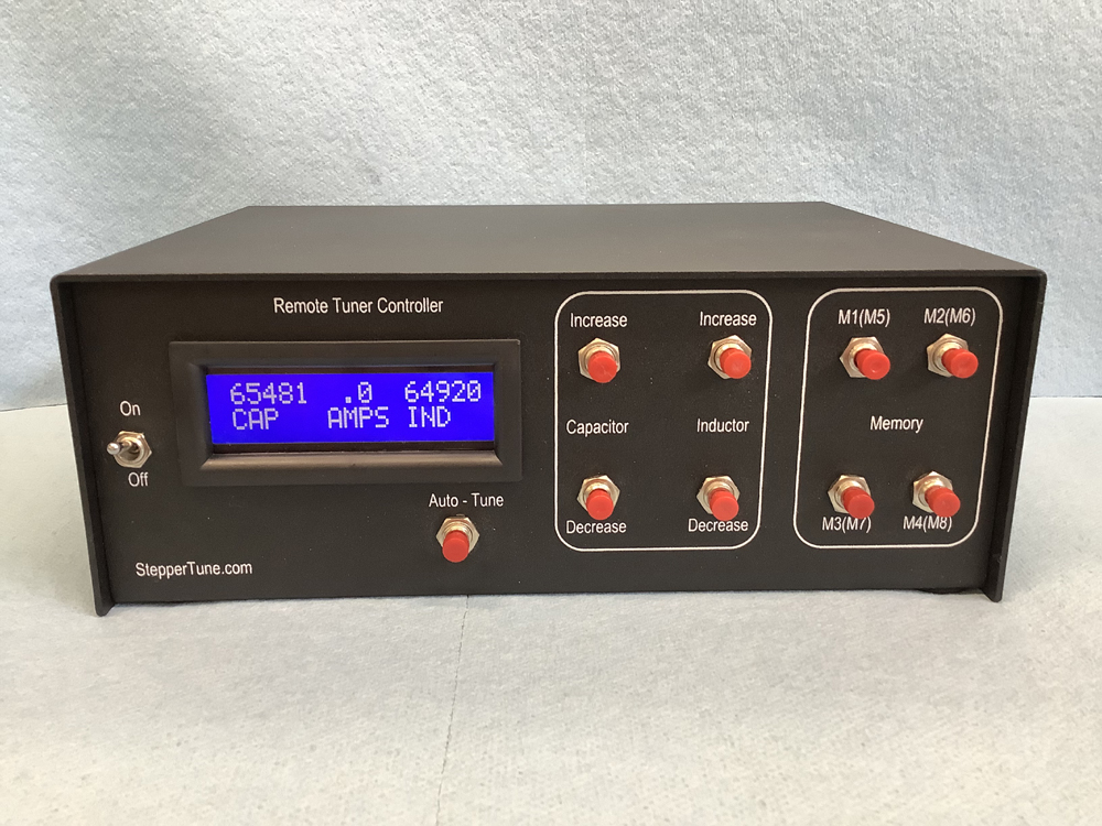
Balanced ATU-Two Stepper Motor Control
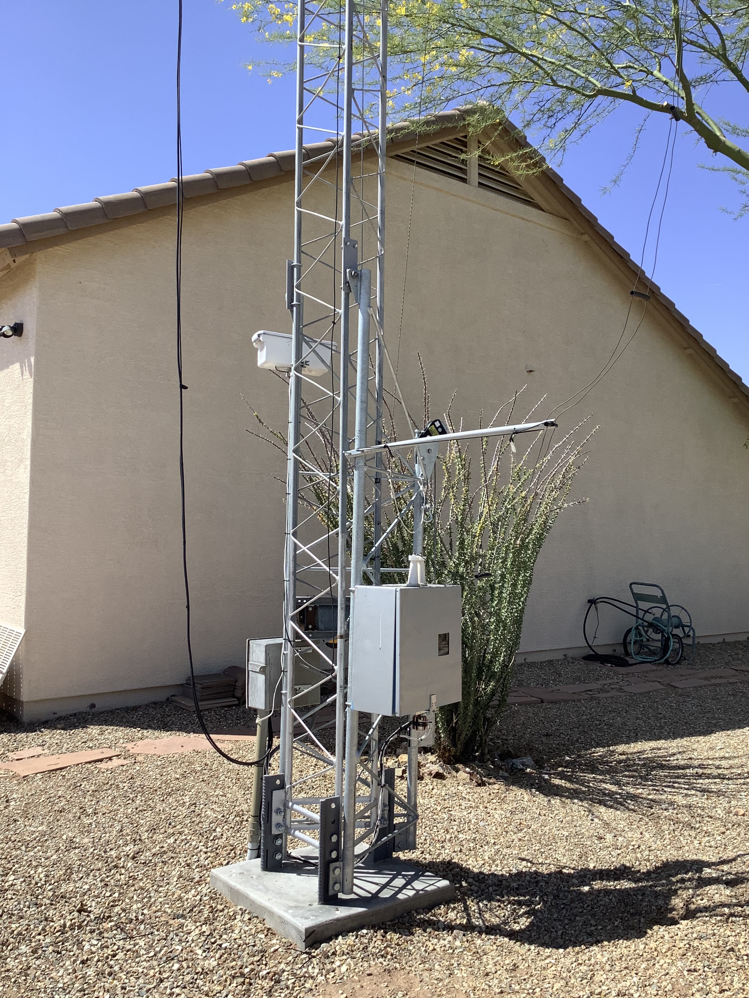
Remote ATU located at the K7EMF Ranch
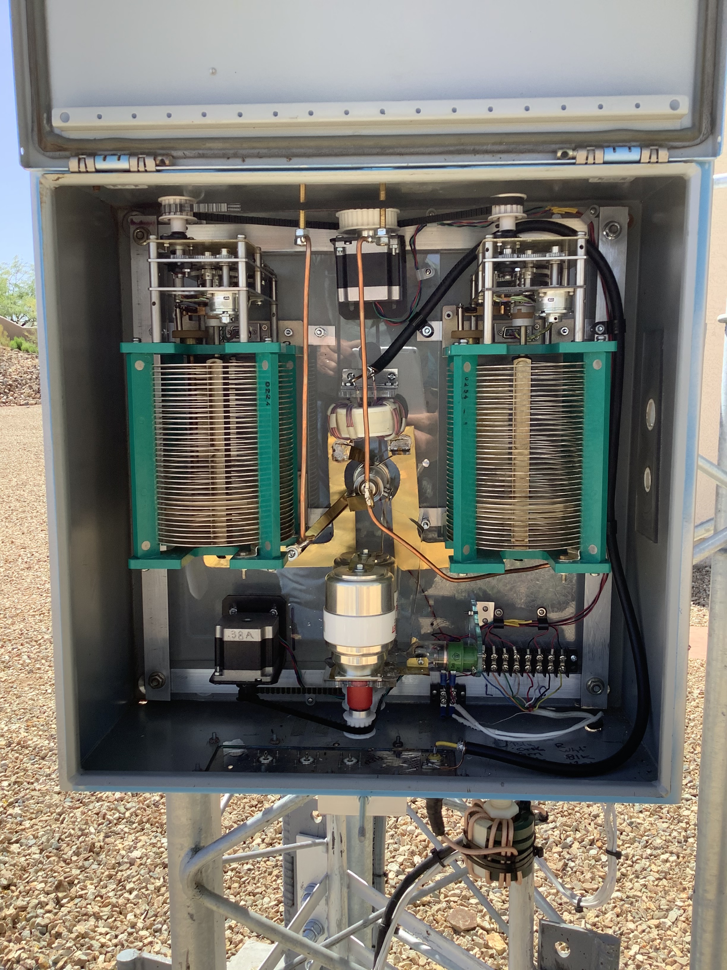
Balanced ATU Feeding TrueLadderLine at K7EMF QTH
