|
StepperTune-BT Features:
--New Model Also Capable Of Controlling Three Switching Relays Within The ATU (Such As A Balanced Tuner)
--Designed To Control Two Stepper Motors For Controlling A Remotely Located Antenna Tuner.
--May Remotely Control Tuning Capacitor For Magnetic Loop.
--Control Cable May Be CAT5 Cable Up To 200 ft while Using A 12 Volt Power Supply.
--Cable Lengths Greater Than 200 ft May Be Realized Using A Supply Voltage Up To 24 Volts DC.
--Eight Memory Locations For Both Steppers.
--Stepper Motor Current Control and Stepper Motor Current Displayed. Capable Of Up To 2 Amps of Stepper Drive Current.
--Stepper-Over Current/Over Temp Shutdown Protection.
--“Jog Mode” To Easily Fine Tune Either Stepper Motor.
--Stepper Motor Speed Easily Programmed.
--Limits Set In Software To Limit Travel
--Remote Control Interface DB9 Option: $135
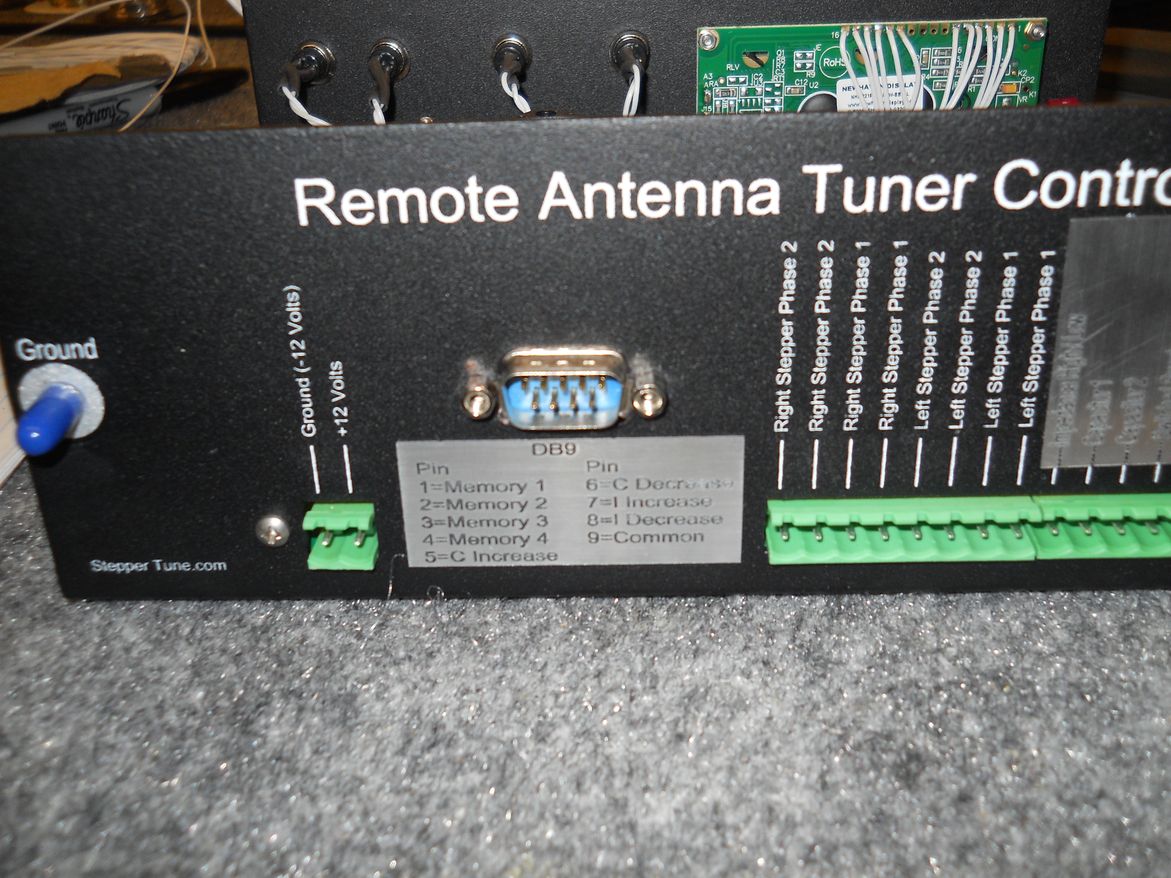
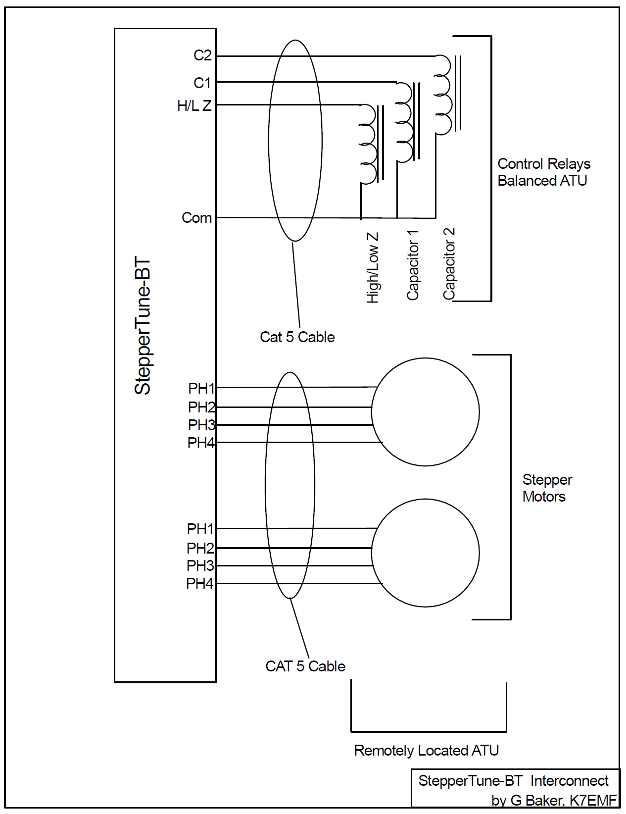
 This Controller Is Capable Of Driving Two Stepper Motors Over 8 Conductor Cable (typically CAT5 cable). Current Control Is Necessary To Protect The Stepper Motors. The Display Shows Stepper Motor Position In Terms Of Step Number And Current Used For The Latest Stepper Motor Movement. This Unit Is Extremely Accurate And Re-Settable. It Utilizes Replaceable H-Driver Modules Which Are Current And Temp Protected. This new model provides full control of a balanced tuner (addition of three relay control outputs, 2A Source Current). The relay control outputs are associated to the memory positions. Therefore, once programmed, the operator does not have to worry about vacuum relay positions within the ATU! Switching is accomplished automatically. See full Description and Manual download at steppertune.com Gary, K7EMF
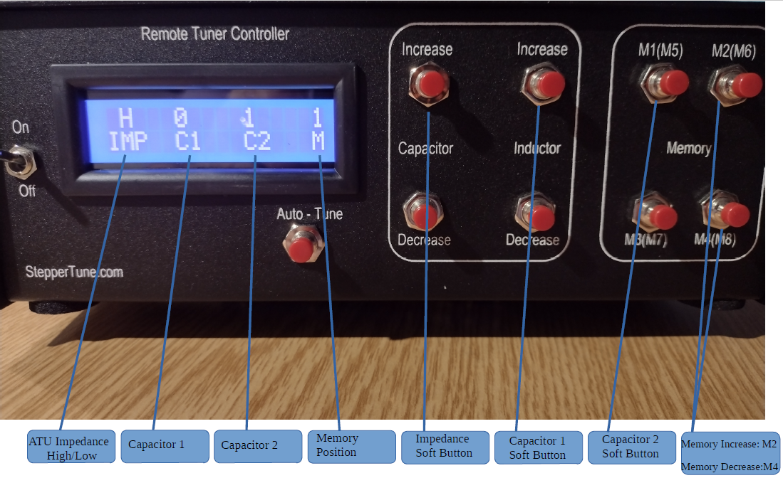
Relays Within The Balanced ATU May Be Controlled Also With StepperTune-BT. During Normal Operation, If The Auto-Tune Button Is Depressed, StepperTune-BT Will Go Into The Relay Control Mode Represented Below. Each Memory Position (1 thru 8) Is Associated With Switch Positions ( H Imp-C1-C2-Memory Position)Pictured Below. While In This Mode, Each Switch Output Is Displayed In Real Time So That The Operator May Use This Mode To Setup The ATU For Each Band. It Is Suggested That At Least One Memory Be Setup For Each Band Of Operation (Example: M1=1945Khz, M2=3885Khz, M3=7290Khz). Each Memory Related Switch Position Is Memorized Into Non-Volatile Memory So that In Operation, The Switch Modes Are Automatically Used For Each Memory Position! During Normal Operation, If The Operator "Touches Up Tuning" Within The Memory Band, The Switch Positions Are Not Changed. The Only Operation That Will Change The Switch Outputs Is If A Different Memory Position Is Initiated. To Exit The Switch Setup Mode, Simply Depress The Auto-Tune Button And StepperTune-BT Is Back In Normal Stepper Mode. Preferred Stepper Motor For ATU: Nema 23 rated at 12V and .5 to 1 Amp.
Video description of StepperTune-BT: Customer Review Video:
|


--------------Setting Up Stepper Motor Current-----------------
------------------------------Configuring Relay Outputs-----------------------------
Reviews
-
EFFICIENCY IS EVERYTHING !!
If you are a wire antenna user, I hope you use a TrueLadderLine 600 ohm open wire product (https://www.trueladderline.com). If not, you are missing out on a great product and the potential for a great antenna system. With the technical help and guidance of Mr. Gary Baker (K7EMF- owner/operator of TrueLadderLine.com and StepperTune.com), I erected a single wire 220 ft multiband wire dipole that is only 34' (agl) at the apex. The ends of the dipole terminate at 20 ft above ground. The antenna is fed with 34 feet of TrueLadderLine 600 ohm open wire feedline. It is connected to an external "remote controlled" ATU (balanced T-Network tuner also designed by K7EMF) located at the base of my antenna center support mast. The ATU uses stepper motors that individually tune a variable inductor and capacitor. I then ran approximately 160 ft of RG-213 for the radios and CAT6 (ATU controller) cable into my radio room. Inside the radio room, I use another great K7EMF product, a StepperTune.com controller (https://steppertune.com/steppertune/) As aforementioned, the CAT6 cable is used to tune the ATU remotely. With this K7EMF-designed system, I can tune my wire dipole effortlessly from 160m through 15m with NO GAPS. My SWR on any of the bands is absolutely nothing, and the efficiency of the antenna system is beyond belief. No high SWR on the feedline and greater efficiency on the antenna - I am in ANTENNA HEAVEN! Thank you, Gary K7EMF! 73 de John A Schwamm KA7TXS
-
Quality balanced tuner
I've long waited for this type of product to become available and it is finally here. It is capable of tuning my 160 dipole with 1.0 SWR on 16080, and 40 with no problem. I can cover those entire bands with the 8 memories in the Steppertune controller. If you use this tuner you won't go back to anything else.


