-- StepperTune-BT Setup Videos--
Click on this link to download two Videos detailing setup for
the StepperTune-BT controller:
https://drive.google.com/drive/folders/1lvc78N9CL7PW_Y966Q71Fc3HTHAikqug?usp=sharing
---------------------------------------------------------------------------------------------
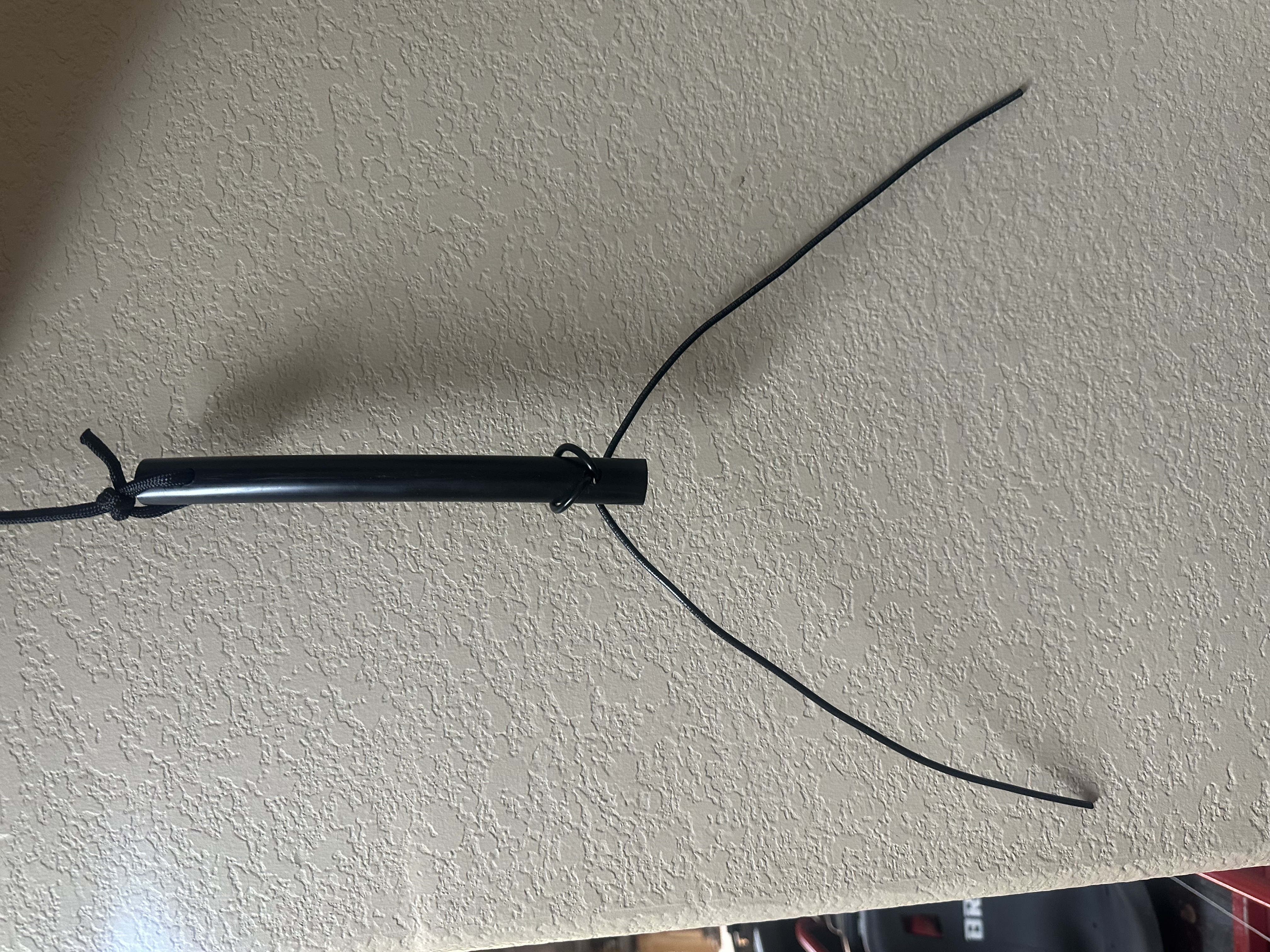
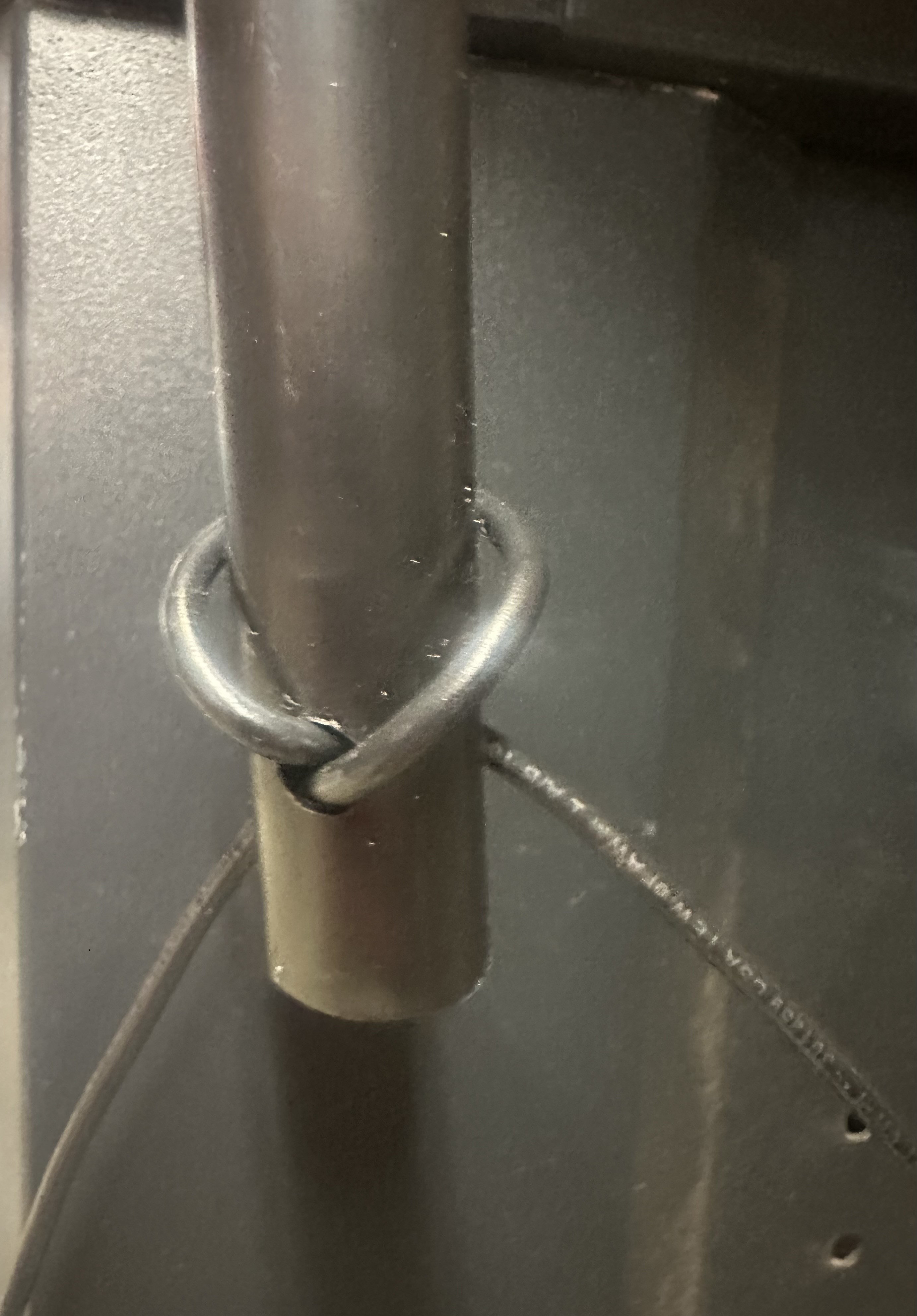
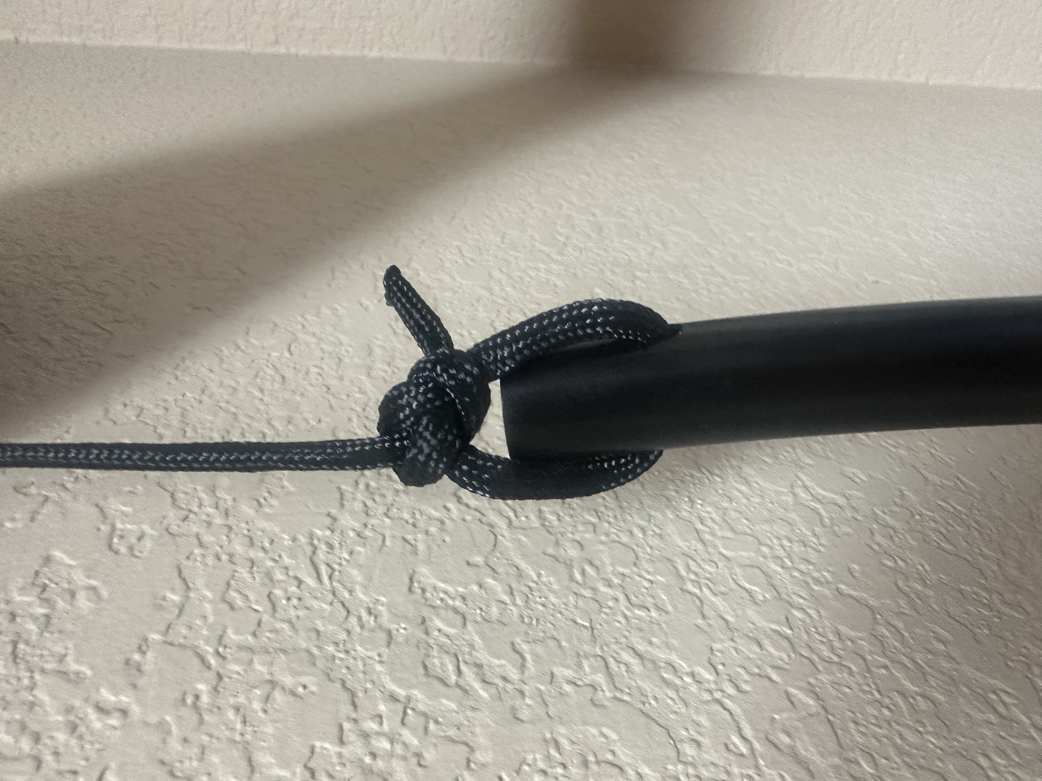
Loop Antenna Insulator Install
==============================================================
ST-1 Stepper Motor Kit
The ST-1 is designed to attach to the Palstar BT1500A ATU. The ST-1 attaches to the front panel of the BT1500A with existing
mounting screws (no new holes required!).
Assembly Steps:
1) Remove front panel mounting screws and slide panel out (after removing control knobs).
2) Remove the Inductor counter assembly and install supplied 1/4" shaft.
3) Install Cog Pulley on the new shaft installed in step 1.
4) Remove drive assembly from the Capacitor and install supplied bushing with the three 4-40 screws and nuts.
5) Install Cog Pulley on the new shaft installed in step 3.
6) Attach ST-1 assembly to the front panel with the front panel mounting screws (8-32 x 1/2" supplied).
7) Perform a stepper motor current setup with StepperTune.
8) Adjust each stepper motor for belt tension and alignment.
9) Adjust stepper motor speed for both the capacitor and inductor to the lowest speed and still have reasonable speed to make adjustments. Note: if the speed is too high, the stepper motor will miss steps!
9) Add capacitor switching wires (supplied) to the terminal strip for remote control of impedance switching.
10) Setup capacitor and inductor limits with StepperTune.
11) Use StepperTune to tune the ATU for each frequency of operation desired and memorize in the eight memory positions.
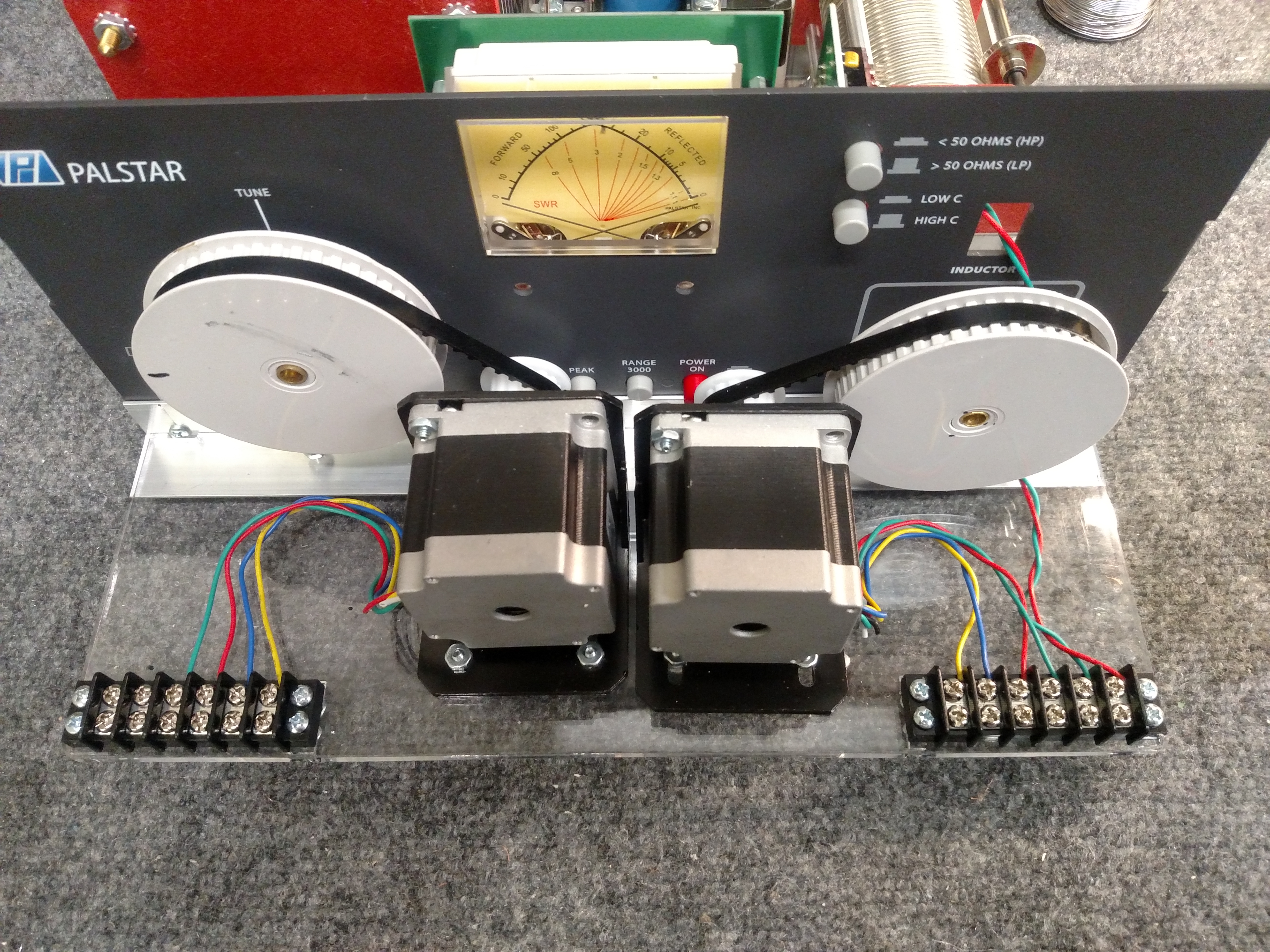
ST-1 Stepper Motor Kit (BT1500A not included)

ST-1 Stepper Motor Kit (BT1500A not included)
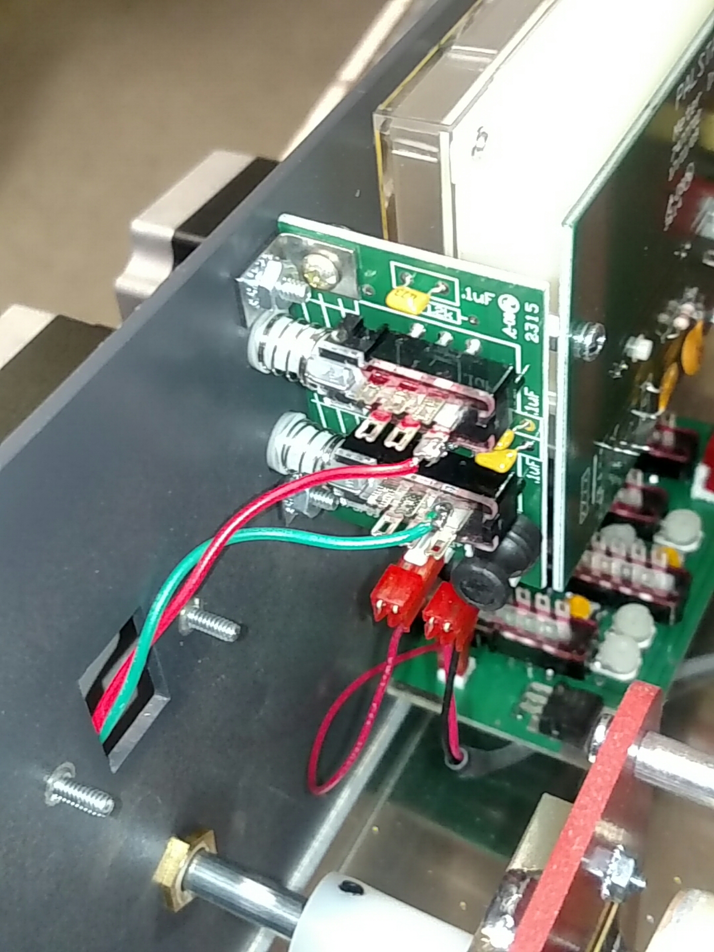
External Capacitor Control Connectons
========================================================================================================================================================================================
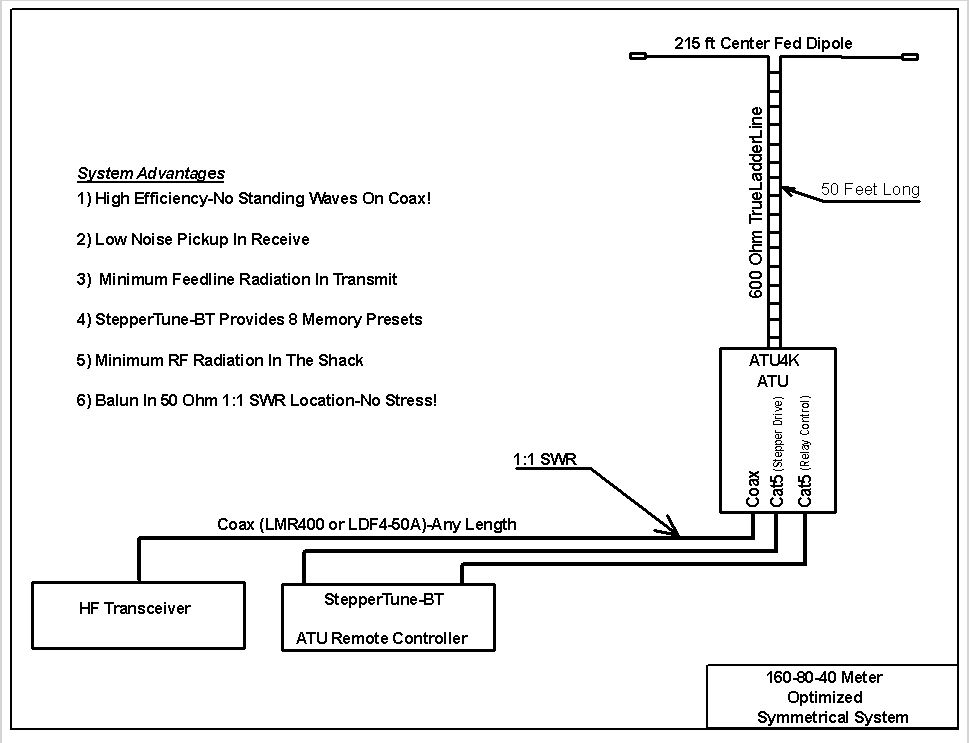
ATU4K Antenna Tuning Unit Wiring and Interconnect Schematics
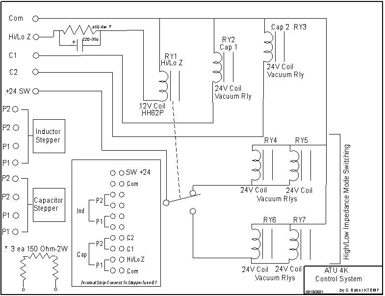
ATU4K Balanced Antenna Tuner Control Schematic
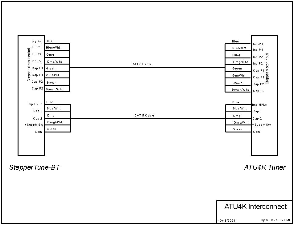
ATU4K Interfaced To StepperTune-BT
